Here at work we’ve got a no-break that’s been untouched since it was bought 5 years ago. This wouldn’t be a major issue, except it is an enormous 10 kVA 3-phase no-break that uses 80 sealed lead acid (SLA) batteries.
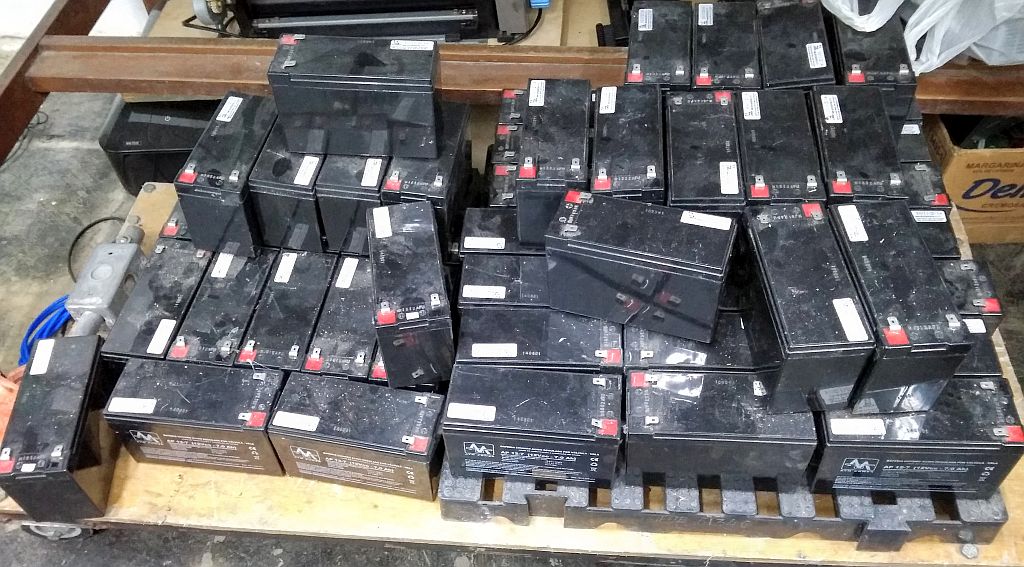
A quick measurement shows us they have around 5-7 Volts, so they’re definitely “dead”. When searching for a way to recover them, I came across the video below that tells to open them up, refill with rain water, and then apply pulsed voltage to make them usable again. According to the video, the batteries “die” due to a chemical process called sulfation that happens inside the cells when the battery is left unused for a long time, and prevents them from being recharged.
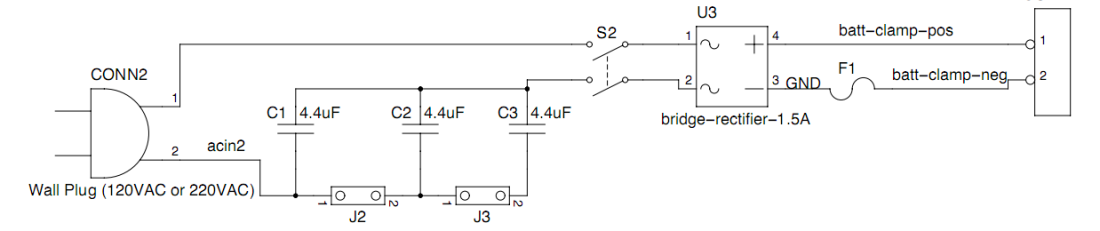
The device that supplies the pulsed voltage is called DA PIMP, and was developed by the video’s author. Fortunately it’s an open-source project, available here. Basically, it gets the mains voltage, rectifies it and limits the current by using capacitors in series with the diode bridge. It also has an ATMega microcontroller that measures the battery voltage and displays it on a display.
I thought it was a cool idea, and decided to build it and add some features. The DA PIMP Plus was born.
DA PIMP Plus
First, instead of 7-segment displays, I switched to a 16×2 alphanumeric LCD to show more information. Then I added a current sensor, and relays to toggle between charge, discharge and float modes. On the LCD is also shown how much time has passed since the circuit entered the selected mode. Here’s the new schematic.
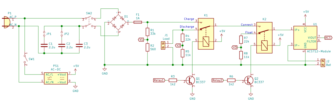
Each mode has a voltage divider (R1-2, R4-5, R7-8) because the voltage on the charge mode can get up to the mains voltage when the desulfation process begins. Therefore, the voltage V1 can’t be measured precisely when the battery goes below 20 V (10% of the input voltage). The desulfation process can be further reverted if the battery is cycled (charged and discharged) a few times, so I added the discharge mode. A car light bulb can be used as a load: a 15 W lamp drains up to 1.25 A. Finally, the float mode is used to measure the stand-by voltage of the battery. A good one must have at least 11 V.
Here are some considerations on the max charging current. Sklar’s project uses 4.4 µF capacitors and says the max currents are 183/366/550 mA for 110 V (double for 220 V), depending on how many caps are in parallel (determined by jumpers J2 and J3). I thought he was right and used 2.2 µF caps to keep the same charging currents (mains voltage is 220 V here). But while testing the circuit with all three caps in parallel (6.6 µF total), I noticed the max current was 240 mA, less than half of what was expected (550 mA). I thought on how he got those values, and I guess he used Ohm’s law, multiplying the AC voltage by the capacitor impedance (Xc = 2 × π × frequency × capacitance), which is not correct. The capacitor current formula is i(t) = C × dv(t)/dt, so for a 60 Hz 220 Vac voltage, v(t) = 220 × sqrt(2) × sin(60t), and therefore i(t) = C × 220 × sqrt(2) × 60 × cos(60t). Making C = 6.6 µF we get max(i(t)) = 6.6 × 10^(-6) × 220 × sqrt(2) × 60 = 123 mA. Since we’re using a full bridge rectifier, the max current is double of this value, 246 mA.
After the circuit was tested, I’ve built it on a perf board and placed it on a wooden base. It looks ugly but works.
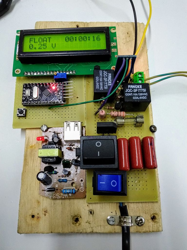
The brown board on the left is a 5 V power supply, turned on by the blue switch. The big black switch connects the mains voltage to the rectifier. The small module on the upper part that has 3 wires coming out is the current sensor, an ACS712-5A module. The terminal block on the top right is used to connect the load of the discharge mode (a 15W car light bulb). I’ve used an Arduino Pro Mini as the central processor.
Desulfation process
In case you skipped the video, here’s a quick step-by-step on how to recover a SLA battery. Do this procedure on an open and ventilated place, wear gloves and preferably some protective goggles when handling the battery and fluids.
- Clean the battery;
- Remove the top cover. It may not come off easily neither in one piece if it’s properly glued (this was my case);
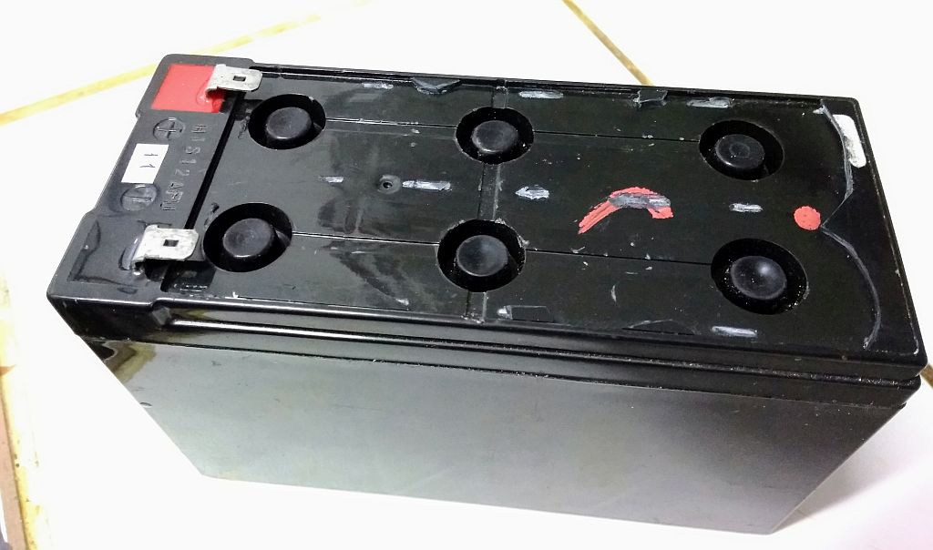
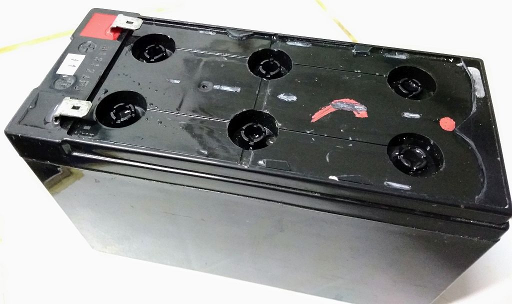
Top cover removed - Remove the rubber caps of each cell;
- Use a syringe to fill each cell with rain/distilled/de-ionized water. Here I had to pour 15 mL on each one;
Cells filled with distilled water - Turn on DA PIMP Plus (blue switch) and wait for the calibration process to end;
- Connect the leads on the battery terminals (positive on positive, negative on negative);
- Switch to charging mode (CHARG);
- Turn on SW2 (big switch);
- Leave the battery charging until the voltage drops to 12 V. During this process the battery will gas and water may spill. If that happens, remove the excess with the syringe;
- Switch to discharge mode (DISCH) and check if the voltage doesn’t drop below 11 V. If it does, switch back to charging mode.
WARNING: do not handle the leads while SW2 is on!
The video below shows the beginning of the desulfation process. Note that the battery voltage starts at 130 V and drops slowly.
Normal charging process
After the voltage has dropped to 12 V, you may switch to a faster charging method, using a battery charger, or if you have an adjustable bench power supply that can limit the output current, you can follow these steps:
- Set the output voltage to 14.4 V and the current limit to 0.25C (C is the battery capacity in Ah);
- Connect the battery (positive to positive, negative to negative);
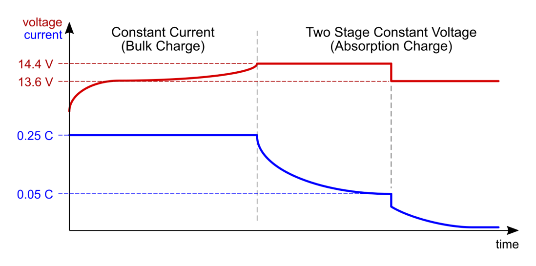
- The first charging stage will be constant-current: the battery will drain the max current you set on step 1, and the voltage will slowly rise up to 14.4 V, and stay on this level for a while;
- Then, the second charging stage will begin seamlessly: constant voltage, and the current will slowly drop.
- When it gets below 0.05C, reduce the voltage to 13.6 V. At this point the battery will be 70-80% charged. The current will keep dropping;
- Keep the battery on this mode as long as you wish. When the current value gets to a plateau, i.e. it doesn’t drop anymore for a long while, you may stop the charging process.
If you have a 7 Ah battery for example, you must set the output current to 0.25 × 7 = 1.75 A on the first step, and reduce the voltage on step 5 after the current reaches 0.05 × 7 = 0.35 A.
The graph below illustrates this charging process. It was based on AG102 datasheet, a battery charger module (described on Morgan’s resource, linked at the end).
Final words
I’ve made the schematics and the Arduino firmware available at my GitHub repository.
https://github.com/gutierrezps/da-pimp-plus
I strongly recommend you to visit Mikey Sklar’s project page, since it has a detailed explanation on how the circuit works, how to use it properly, and also some frequently asked questions.
The voltage values were based on a sealed lead acid, 6-cell 12 V battery. Check the resources linked below for different voltages.
Resources
- Mikey Sklar. DA PIMP 2. <http://mikeysklar.blogspot.com/p/da-pimp-battery-desulfator.html>
- Battery University. BU-403: Charging Lead Acid. <https://batteryuniversity.com/index.php/learn/article/charging_the_lead_acid_battery>
- Tony Morgan. Guide to charging Sealed Lead Acid batteries. <http://www.silvertel.com/images/technical-articles/charging_sealed_lead_acid_batteries.pdf>
- Itacanet.org. A Guide to Lead-Acid Batteries. <https://www.itacanet.org/eng/elec/battery/battery.pdf>
- Electrical Engineering Stack Exchange. What is a safe max. discharge rate for a 12V lead acid battery?<https://electronics.stackexchange.com/q/130580/46069>
- ATM Power. AP 12-7 SLA Battery Datasheet (portuguese). <http://www.atmpower.com.br/pdf/folheto7Ah.pdf>

Any way you can put together a parts list? Debating on doing a Da Pimp V2 or this one
LikeLiked by 1 person
Sure! I’ve added on the GitHub repo.
LikeLike
It would be better if there was a ready printed circuit board in gerber format.
LikeLike
I will be working on some improvements on the measurement part, so it’s not entirely ready yet.
LikeLike
Thanks for sharing your knowledge. I reached here trying to repair a “DA PIMP” that was burned. After replacing all components on the board, nothing happened, so I thought it could be the programming of the atmega chip or the motherboard itself (measuring part, not charging part).
I think yours is a better solution/improvement. I will try to build your DA PIMP Plus soon.
Thanks again
LikeLiked by 1 person
You’re welcome!
LikeLike
Just curious why C1-C3 are before SW2 instead of after does it matter? and if I enclose it in a box is there any problem running JP1 and JP2 to two toggle switches with short lengths of wire?
LikeLiked by 1 person
1. No, it doesn’t matter if the caps are before or after SW2, the capacitors won’t charge if the switch is open.
2. The only thing you should be aware is if the toggle switches you’re using can provide insulation for 220V. The charging currents are small, so the voltage insulation parameter is the main requirement.
LikeLike
Any updates on your improvements on the measurement part? I’m thinking of designing a PCB from your schematic and would like to use the most up to date design.
LikeLike
My goal is to come up with a new design until the end of the year. The problem with the current approach is the low precision when the circuit is in charge mode, since it can go up to 220V. I’m thinking about using optocouplers to measure two voltage ranges, one is 0-20V and the other is 0-220V, so a higher voltage in the low range will simply saturate the optocoupler output.
LikeLike
Will you ever be making a kit or an asembled unit for those of us who want an easy way to do this..
LikeLike
Maybe next year, after I improve he measurement part.
LikeLike
hola gabriel necesito desulfatar bateria marca optima …puedo comprar tu equipo? si no puedo cual equipo me recomiendas ? que no sea costoso ? gracias
LikeLike
Unfortunately I’m not selling it, and I don’t know any related equipment.
LikeLike
Hi Gabriel.
I know you stated in another post that you wouldn’t sell this, but I can’t find da Pimps anywhere for sale and wouldn’t trust myself to build my own.
Any chance you’d build/sell your improved one? Please email. Thanks!!!
LikeLike
I’m sorry, but I can’t see that happening in the near future. If anything changes I will make a new post and get in touch.
LikeLike
Hi Gabriel,
i think this is a great project, i made one by my self im just struggling with arduino … it just wont work. i uploaded program to 3 arduinos but non of them worked … dont know where. Platformio says everything is fine … but when i connect arduino to display its just one line on bottom of display. .. im getting headache 🙂 any help needed .. thanks
LikeLike
Some things to check:
– Jumpers/wires OK? Maybe there’s a bad jumper, check with a multimeter.
– Wiring OK? Check the connections again, or undo and redo the wiring
– Display OK?
– Isolate the problem: first connect only Arduino and display, and then gradually connect other blocks.
LikeLike
i tried to connect only display but it didnt help at all. Same thing happened. Only bottom line of display is filled. i checked connections and everything seems to be fine.
LikeLike
It seems your display is broken. Without changing connections, load a LCD test firmware.
LikeLike
Hi Gabriel,
i know its a long time i responded but here’s update: I checked everything like 10 times … connected only arduino and display as u adviced … and it isnt working. So i’ve tested LCD test “Hello World” with Arduino IDE and wow it works !!! So LCD and arduino is OK. When i uploaded your souce code with platformio, its not working and it seem reseting every second … so i suppose theres some glitch. any ideas ? thanks
LikeLike
Gabriel Gutierrez,
Thanks for putting all this information together. I’ve been meaning to do this myself. I have NO experience with electronics but am a tinkerer. I like to learn new things and figure things out – even though I’m an old dog (grey hairs 🙂 ). Any advice on getting started? Or maybe writing up a little more detailed step by step on what to do? I know it is a big ask given it’s your personal time. All that said, thanks for this write up. I’m going to get started by creating a bill of materials and ordering the parts. As well as buying a soldering iron. Ha ha! This will be an adventure. As well as figuring out how to program an adriano. Lot’s to learn :).
LikeLiked by 1 person
After you gather some basic soldering skills, you can easily assemble this circuit on a perf board, as I did, by following the schematics. Please be very careful since you’re dealing directly with mains voltage! Double check your connections and solderings before plugging into the power outlet, and absolutely do not plug the Arduino to your computer while the circuit is connected to the mains, since there’s no voltage insulation anywhere.
LikeLike
Gabriel Gutierrez,
I typed my note above before checking out the github where you have lots more information. :). Never heard of github before. Again, learning. I think I might involve my high school son in on this. Good father / son project. Plus, I could probably use some of his computer skills.
LikeLiked by 1 person
Good luck!
LikeLike